
WHAT IS A VFD DRIVE AND WHY YOU NEED ONE
October 29, 2024
What is a Variable Frequency Drive (VFD)
A Variable Frequency Drive (VFD) is an advanced electronic device designed to control electric motors’ speed, torque, and direction by regulating the frequency and voltage supplied to the motor. The primary function of a VFD is to adjust the motor’s input frequency, allowing it to operate at variable speeds. This control over motor speed makes VFDs ideal for applications requiring precise motor operation, such as conveyor systems, pumps, fans, and HVAC systems. VFDs enhance the flexibility and efficiency of various industrial processes by providing control over motor speed.

VFDs play a crucial role in process control, allowing for precise adjustments to motor speed. This is particularly important in processes that require consistent, adaptable, or sensitive operations. For instance, in water pumping applications, a VFD can ensure a steady water flow by adjusting pump speed in response to changes in demand or system pressure. This level of control leads to more stable operations, reduces product variability, and helps meet specific process requirements.
Types of VFDs
There are three main types of Variable Frequency Drives (VFDs), each with unique characteristics and applications suited to different operational needs:
1. Voltage Source Inverters (VSI):
Voltage Source Inverters are among the most used VFD types due to their simplicity and cost-effectiveness. VSIs control motor speed by adjusting the input voltage supplied to the motor, making them relatively straightforward to design and operate. They are widely used in applications with sufficient essential speed control, offering reliable performance at a lower cost. However, VSIs may have limitations in dynamic response and precise torque control, making them best suited for applications that do not require high torque output.
2. Current Source Inverters (CSI):
Current Source Inverters are known to provide higher torque performance, making them ideal for heavy-duty and high-inertia applications, such as in large compressors, cranes, and hoists. Unlike VSIs, CSIs adjust the motor’s current to control speed and torque. This design gives CSIs the advantage of better handling sudden load changes and maintaining stable torque output, which is crucial in demanding environments. Although they are more complex and often more expensive, CSIs excel in situations that require robust torque control and are highly valued in industrial applications with significant starting and stopping forces.
3. Pulse Width Modulation (PWM):
Pulse Width Modulation is the most popular and widely used type of VFD. PWMs use a sophisticated method of controlling the frequency and voltage by adjusting the width of electrical pulses sent to the motor. This approach enables precise speed control, high energy efficiency, and lower power loss, making PWMs ideal for various industrial applications. Their flexibility and efficiency make them suitable for everything from simple fans and pumps to complex conveyor systems and HVAC units. PWM drives are known for their smooth motor operation, reduced harmonic distortion, and adaptability to various motor types, making them a versatile and efficient choice for most VFD applications.
How Does a Vfd Drive Work?
The basic principle of operation involves five steps:
- Rectification – The VFD first converts the incoming AC (Alternating Current) power to DC (Direct Current) using a rectifier. The rectifier consists of diodes or thyristors that allow current to flow in one direction, creating a pulsating DC voltage.\
- DC Bus – The DC power is then smoothed out using DC bus capacitors, which filter out ripples, providing a stable DC voltage.
- Inversion – The stable DC voltage is then converted back to AC using an inverter. The inverter is made up of Insulated Gate Bipolar Transistors (IGBTs) or similar semiconductor switches that can turn on and off rapidly.
- Pulse Width Modulation (PWM) – The inverter creates an AC output with a variable frequency and voltage using Pulse Width Modulation (PWM)
- Output to Motor – The modulated AC output is supplied to the electric motor. By adjusting the frequency (Hz), the motor speed is controlled because the speed of an AC motor is proportional to the frequency of the power supply.
Advantages of Variable Frequency Drive Panels
Variable Frequency Drive (VFD) Panels offer numerous advantages in industrial settings, where controlling motor performance and efficiency is essential for optimized operations. Here are the benefits that VFD panels provide:
1. Improved energy efficiency:
VFD panels enable motors to run optimally based on real-time demand, avoiding unnecessary full-speed operation. By matching motor output to application needs, VFDs reduce energy consumption significantly, which can result in substantial savings on electricity costs, especially in systems that experience variable load requirements.
2. Precise motor speed control:
VFDs allow operators to precisely control motor speed, which is crucial in applications that require gradual acceleration or deceleration. This level of control enhances process accuracy and consistency, ensuring that operations can meet specific parameters and maintain quality standards, even in complex processes like mixing, pumping, and conveying.
3. Reduced mechanical stress on motors:
VFD panels help minimize wear and tear on mechanical components by avoiding sudden starts and stops. By allowing smooth acceleration and deceleration, VFDs reduce the stress on motor bearings, shafts, and other mechanical parts, which would otherwise suffer from high torque loads and stress in fixed-speed applications.
4. Enhanced process automation:
By integrating VFD panels, industries can achieve higher levels of automation by seamlessly adjusting motor speeds to respond to varying process demands. VFDs are compatible with advanced control systems, making it easy to automate processes, increase productivity, and adapt quickly to operational changes, which is especially beneficial in manufacturing and processing plants.
5. Lower operational costs:
VFD panels contribute to lower overall operational costs by improving energy efficiency and reducing mechanical stress. These cost savings come from reduced energy bills and decreased downtime and repair needs, as VFDs help maintain smooth and reliable operations.
6. Extend equipment lifespan:
VFDs allow motors to run at speeds suited to the load, contributing to equipment longevity. Motors operating at optimal speeds experience less heat generation, vibration, and mechanical wear, resulting in a prolonged lifespan for the motor and associated machinery. This durability makes VFD panels a worthwhile investment for any industry aiming to reduce capital expenditures on motor replacements.
7. Minimize maintenance requirements:
VFD panels help minimize maintenance requirements by controlling motor operation more effectively and preventing excessive wear. Reduced wear on mechanical parts means fewer repairs, less frequent maintenance checks, less downtime, and greater overall productivity.
Variable Frequency Drive (VFD) Working Principle
A VFD controls the speed and torque of an AC electric motor by varying the frequency and voltage of the electrical power supplied to the motor. It does this through a series of electronic conversions, using advanced semiconductor devices. The working principle of VFDs is as follows:
- Power Conversion Stages
- AC to DC Conversion : Input Stage – The VFD receives AC power from the utility grid. It passes through a rectifier, which converts the incoming fixed-frequency AC power into DC power. Output – The output of the rectifier is a pulsating DC voltage
- DC Smoothing: DC Bus Capacitors – The pulsating DC from the rectifier is smoothed out using large capacitors. These capacitors store and release energy to create stable and consistent DC voltage. This ensures a clean and steady DC supply for the next stage of conversion.
- DC to Variable AC Conversion (Inversion): Inverter stage – The smoothed DC voltage is converted back to AC using an inverter. The inverter uses Pulse Width Modulation (PWM) to create an output AC waveform. PWM works by rapidly switching the IGBTs on and off, creating a series of voltage pulses. By varying the width and frequency of these pulses, the inverter simulates a sine wave input with controlled frequency and voltage.
- Output to Motor – The modulated AC power from the inverter is then supplied to the motor. There are two control methods used for output to motor. Frequency Control: By varying the frequency, the VFD controls the motor speed because the speed of an AC motor is proportional to the frequency of the power supply. Voltage Control: The VFD simultaneously adjusts the output voltage to maintain a constant Voltage-to-Frequency (V/f) ratio, ensuring efficient motor performance and torque control.
- Key Control Methods
- V/f Control (Volts per Hertz) – maintains a constant ratio between voltage and frequency for consistent torque.
- Sensorless Vector Control – provides better torque control and dynamic response without using a physical sensor.
- Closed-Loop Vector Control – uses a feedback sensor to provide precise speed and torque control.
- Protection and Safety Features
- Overload Protection – prevents motor damage due to overcurrent
- Overvoltage and Undervoltage Protection – ensures stable operation during voltage fluctuations.
- Thermal Protection – protects the VFD and motor from overheating.
Applications of Variable Frequency Drives
Variable Frequency Drives (VFDs) are extensively used across various industrial and commercial applications to optimize motor performance and improve overall process efficiency. By precisely controlling motor speed and adjusting power output to match demand, VFDs offer enhanced control, energy savings, and operational flexibility in numerous applications, including:
-
- HVAC Systems: In heating, ventilation, and air conditioning systems, VFDs regulate fan and pump speeds to maintain optimal airflow and temperature without running motors at full speed. This regulation reduces energy consumption, lowers noise levels, and increases the lifespan of HVAC components by minimizing wear.
- Conveyor Belts: In manufacturing and material handling applications, VFDs are essential for managing the speed and direction of conveyor belts, ensuring that materials move at the appropriate rate to support production lines. This precise control helps avoid product damage, enhances safety, and allows for flexibility in processing times, adapting to various production demands.
- Pumps: VFDs are highly valuable in applications involving pumps, such as water and wastewater treatment, irrigation, and chemical processing. By controlling pump speed, VFDs adjust flow rates and pressure to meet system requirements, reducing energy costs and preventing water hammer and other mechanical stresses, which can damage pipes and equipment.
- Fans: In many industries, VFDs control fan speeds, adjusting airflow to meet ventilation or cooling needs. This capability is particularly beneficial in industrial plants, data centers, and agricultural environments, where stable air quality or temperature control is crucial. VFDs enable these systems to run efficiently, reducing energy waste and enhancing environmental control.
- Compressors: VFDs help compressors maintain precise pressure levels by adjusting motor speed based on demand. In applications like refrigeration, air conditioning, and pneumatic tools, this control enables compressors to operate more efficiently, reducing energy usage and prolonging compressor life by preventing unnecessary cycling.
Engineering and Design Considerations for VFD Panels
Several key considerations must be addressed when designing Variable Frequency Drive (VFD) panels to ensure optimal performance, reliability, and safety. These considerations are critical for supporting the VFD panel’s functionality in diverse industrial environments and meeting the specific requirements of the motor and application. Important design aspects include:
-
- Proper Ventilation for Heat Dissipation: VFDs generate significant heat during operation, which can impact their performance and lifespan if not managed effectively. Ensuring that the VFD panel has adequate ventilation or cooling mechanisms, such as fans or heat exchangers, is essential to maintain a stable temperature within the enclosure and prevent overheating.
- Appropriate Sizing of Components for the Motor Load: It is crucial to select components with the correct ratings for the motor’s load and application requirements. Properly sized VFD components, such as fuses, circuit breakers, and wiring, help prevent overloading and ensure efficient power delivery, reducing the risk of failures and extending the panel’s operational life.
- Ensuring Compatibility with the Electrical System: Compatibility with the existing electrical system is vital for seamless integration and stable operation. Factors like voltage, phase, and grounding must align with the facility’s electrical specifications to avoid electrical disturbances, minimize harmonic distortion, and ensure safe operation.
- Implementing Protective Features: Protective features like surge protection, overload protection, and fault monitoring systems enhance the panel’s resilience against electrical anomalies and operational issues. Surge protection shields sensitive VFD components from voltage spikes, while fault monitoring allows for quick detection and resolution of potential issues, reducing the risk of equipment damage and costly downtime.
- Attention to Environmental Factors: Environmental conditions such as dust, moisture, and temperature fluctuations can significantly affect VFD panel reliability. Enclosures with appropriate IP ratings and incorporating dust filters or seals help protect the panel from contaminants and moisture, making it suitable for long-term use, even in harsh environments.
Incorporating these considerations ensures that VFD panels can operate efficiently, handle the motor load effectively, and maintain durability under various operating conditions.
Conclusion
Variable Frequency Drives (VFDs) offer substantial benefits across various industrial and commercial applications, particularly in energy savings, precise motor control, and extending the life of valuable equipment. By adjusting motor speed to match operational demands, VFDs significantly reduce energy consumption, which can result in marked cost savings and help facilities meet sustainability targets.
The enhanced motor control provided by VFDs allows for smoother acceleration and deceleration, reducing mechanical stress on equipment and minimizing wear. This capability extends the lifespan of motors and related components and decreases maintenance needs, leading to reduced downtime and lower repair costs. Furthermore, VFDs are highly versatile, supporting various applications—from pumps, fans, and conveyors to complex manufacturing and process systems—making them essential for efficient and adaptable operations.
By offering reliable performance, VFDs contribute to more stable and cost-effective operations, support energy-efficient practices, and align with modern sustainability goals. Their role in optimizing processes and conserving resources makes VFDs a valuable investment for industries that enhance operational productivity and reduce environmental impact.
Introduction to Motor Starters
- What is a Motor Starter?
A motor starter is an electrical device used to safely start, stop, and protect an electric motor. It regulates the initial inrush current, preventing damage from high starting currents. Motor starters typically include a contactor for switching power and an overload relay for protection against overheating. They can be manual, magnetic, or soft starters, depending on the application and level of control required.
- Importance of Motor Starters in Electrical Systems
Motor starters play a crucial role in electrical systems by ensuring the safe and efficient operation of electric motors. They limit inrush currents, reducing stress on electrical components and preventing damage. Additionally, motor starters provide overload protection, preventing overheating and potential motor failure. By enabling controlled starting and stopping, they enhance system reliability, improve energy efficiency, and extend motor lifespan in industrial and commercial applications.
How Does a Motor Starter Work?
A motor starter is an essential device used to control the flow of electric current to an electric motor, effectively managing its start and stop functions. It also provides crucial overload protection, ensuring the motor doesn’t draw excessive current during startup. This safeguards the motor and any connected equipment from potential damage and prolongs system life.
- Basic Working Principle
A motor starter works by controlling the power supply to an electric motor, ensuring a safe and efficient startup. It typically consists of a contactor for switching power and an overload relay for protection. When activated, the contactor closes, allowing current to flow to the motor. If excessive current or overheating occurs, the overload relay trips, disconnecting power to prevent damage and ensure safety.
- Key Components of a Motor Starter
A motor starter consists of key components that ensure safe and efficient motor operation. The contactor acts as a switch, controlling power flow to the motor. The overload relay protects against excessive current and overheating. A control circuit, including push buttons or switches, manages start/stop functions. Some starters also include short-circuit protection through fuses or circuit breakers for added safety and reliability.
Types of Motor Starters
Motor starters come in various types:
- Direct-on-line (DOL) starter: This type of starter connects the motor directly to the power supply, providing a simple and economical start.
- Stator resistance starter: This reduces the starting current by inserting resistors into the stator circuit, reducing the initial power draw.
- Star-Delta starter: Utilizes a star configuration initially to minimize starting current, then switches to delta for regular operation.
- Soft starter: It gradually increases the voltage to minimize mechanical stress and reduce power surges, protecting motor longevity and preventing outages.
1. Direct-On-Line (DOL) Starter
A Direct-on-line (DOL) starter is a straightforward and widely used motor starting method where the motor is connected directly to the power supply, allowing it to receive the full supply voltage immediately upon startup. This approach enables the motor to reach its rated speed rapidly, making DOL starters popular for smaller motors or applications where the priority is simplicity and low cost. However, this direct connection results in high inrush currents, typically six to eight times the motor’s full-load current. While effective for small motors, high inrush currents can cause mechanical stress on the motor components and produce electrical disturbances in the power supply system, which may impact other devices. This method is most suitable for applications where the power system can handle the high inrush current without issues.
2. Stator Resistance starter
A Stator Resistance starter primarily controls the high inrush current at motor startup by inserting resistors in series with the motor’s stator windings. This insertion of resistance into the stator circuit limits the amount of initial current flowing to the motor, thus reducing the initial torque and current draw. As the motor accelerates and gains speed, the resistors gradually decrease or step down the resistance in the circuit, allowing the current to increase in a controlled manner. This controlled increase provides smoother acceleration and lessens the mechanical and electrical stress on the motor during startup.
This type of starter is especially beneficial in applications where high inrush currents can negatively impact the power system or when a gradual motor acceleration is desirable to protect connected equipment. By controlling the initial current flow, the stator resistance starter minimizes sudden torque spikes, which can lead to wear and tear on the motor components.
3. Rotor Resistance or Slip Ring Motor Starter
A Rotor Resistance or Slip Ring Motor starter is designed explicitly for slip ring induction motors, commonly used in applications requiring high starting torque and smooth acceleration. This type of starter adds external resistance to the rotor circuit during the startup phase. By introducing this resistance, the starter effectively limits the inrush current, which reduces mechanical stress and electrical disturbances. The added resistance minimizes current draw and significantly increases the starting torque, which is highly beneficial for applications that involve heavy loads or need a substantial amount of torque to begin movement, such as conveyor belts, cranes, or mixers.
As the motor accelerates and reaches higher speeds, the starter gradually decreases the external resistance in a controlled manner. This stepwise reduction in resistance allows for smooth, progressive acceleration, ensuring that the motor reaches full speed with minimal impact on its components and connected equipment. The gradual removal of resistance enables precise control over motor performance, particularly during the critical startup period, thus reducing wear and tear and extending motor lifespan.
4. Autotransformer Starter
An autotransformer starter is a motor starter that controls the initial inrush current by reducing the voltage supplied to the motor at startup. This starter is particularly effective when minimizing electrical disturbance and mechanical shock, which is critical, especially in larger motors. The autotransformer consists of taps, or voltage steps, which allow it to initially apply a fraction—often 50%, 65%, or 80%—of the total supply voltage to the motor. By supplying reduced voltage, the autotransformer starter effectively lowers the current drawn by the motor during startup, thereby reducing the strain on the motor and the electrical network.
As the motor begins to accelerate, the autotransformer starter ensures a smooth and controlled operation by gradually increasing the voltage supplied. This is achieved by switching through the transformer taps. The progressive increase in voltage allows the motor to gain speed steadily, avoiding the sudden jolt often experienced in direct-on-line startups. The controlled acceleration provided by an autotransformer starter reduces the impact of high torque on the motor shaft and connected equipment, preserving motor components and extending their operational lifespan.
Once the motor reaches a significant portion of its rated speed, the autotransformer completes the transition by connecting it directly to the entire line voltage, allowing it to operate at full capacity. This method of controlled voltage increase ensures that the motor achieves a smoother, more stable startup and eliminates the risk of power surges that could otherwise disrupt the power network or damage sensitive devices connected to the same supply. Although autotransformer starters are more complex and costly than other starter types, their benefits make them well-suited for heavy-duty industrial applications where equipment protection, energy efficiency, and controlled motor performance are essential.
5. Star Delta Starter
A Star-Delta starter is a widely used method for starting three-phase induction motors, particularly in applications that demand reduced starting current to protect both the motor and the electrical network. The Star-Delta starter operates by initially connecting the motor windings in a star (or “Y”) configuration, which reduces the starting voltage applied to each motor phase. By doing so, the initial current drawn is only one-third of what it would be if the motor were connected directly in a delta configuration. This initial reduction in current significantly lowers the electrical load on the motor and power supply, minimizing the chance of voltage dips or disturbances that can affect other equipment in the same system.
During startup, the motor runs in the star configuration, generating a lower torque sufficient to begin acceleration without overwhelming the motor or the power network. As the motor gains speed and approaches a stable operational level, the Star-Delta starter seamlessly transitions from the star connection to the delta configuration. The motor receives full line voltage in the delta connection, allowing it to reach its rated speed and torque for regular operation.
The Star-Delta starter’s smooth transition from star to delta provides a controlled acceleration, effectively preventing mechanical shocks or excessive torque spikes. This feature is particularly beneficial for high-power motors or those with sensitive load conditions, such as pumps, compressors, and fans. Moreover, the Star-Delta starter is an economical solution, offering a reliable way to control motor startup without the need for complex electronic components or significant additional infrastructure.
6. Soft Starter
A Soft Starter is a sophisticated motor starting device designed to control and gradually increase the voltage supplied to an electric motor during startup, thereby minimizing the high inrush current and mechanical stress typically associated with direct motor starts. Unlike traditional starters that immediately apply full voltage to the motor, the soft starter progressively ramps up the voltage over a set period. This gradual increase enables the motor to achieve its operational speed smoothly, preventing sudden torque and minimizing wear on both the motor and connected machinery.
Soft starters control the initial current using solid-state devices, such as silicon-controlled rectifiers (SCRs), to modulate the voltage applied to the motor. By reducing the voltage incrementally, the soft starter decreases the initial surge of current and significantly reduces the impact on the motor shaft, bearings, and other mechanical components. This smooth acceleration protects the motor from abrupt shocks, lowering the risk of damage to it and any equipment it powers. Additionally, soft starters can be programmed to manage the deceleration of the motor, gradually decreasing voltage as it powers down to prevent sudden stops. This feature is particularly advantageous in applications requiring precise control, as it prevents sudden stops that might otherwise result in mechanical wear or equipment misalignment.
7. Variable Frequency Drive (VFD)
A Variable Frequency Drive (VFD) is an advanced motor control device designed to manage motor speed by precisely adjusting the frequency and voltage supplied to the motor. Unlike traditional starters that provide an on-off function or limit startup current, a VFD gives operators complete control over motor speed and torque, allowing for dynamic adjustments tailored to various industrial applications’ operational needs. By modifying the frequency (measured in Hertz) of the electrical power supplied to the motor, the VFD can regulate motor speed from a standstill up to its maximum rated speed, enabling accurate control over both acceleration and deceleration.
The VFD’s control over speed offers several advantages, particularly in applications where load demands vary or require gradual changes. This adaptability makes VFDs especially valuable in industries using pumps, fans, conveyors, and compressors, where load requirements are not constant. For instance, a VFD can slow down a pump during low-demand periods, saving significant energy by reducing the motor’s speed rather than running it continuously at full capacity. This reduction in motor speed directly influences power consumption, making VFDs a cost-effective solution. They often achieve energy savings of up to 50% in variable load applications, translating into lower operating costs and a more sustainable, environmentally friendly operation.
Comparison of Motor Starters
- Performance & Efficiency Differences
Motor starters impact performance and efficiency based on their type. DOL starters offer simple, direct control but cause high inrush currents, leading to electrical stress. Star-Delta starters reduce starting current but have momentary power loss during switching. Soft starters provide smooth acceleration, minimizing mechanical and electrical stress. VFDs optimize efficiency by adjusting motor speed, reducing energy consumption and enhancing performance in variable-load applications.
- Best Starter for Different Motor Sizes
The best motor starter depends on motor size and application. DOL starters are ideal for small motors (up to 5 HP) where inrush current isn’t a concern. Star-Delta starters suit medium-sized motors (5-100 HP) to reduce starting current. Soft starters work well for larger motors, minimizing electrical and mechanical stress. VFDs provide the best control and efficiency for large motors requiring variable speed operation.
Choosing the Right Motor Starter
Choosing the right motor starter depends on factors like motor size, load type, starting current, and control requirements. DOL starters suit small motors, while Star-Delta starters reduce inrush current for medium motors. Soft starters minimize mechanical stress for large motors, and VFDs offer superior speed control and energy efficiency. Considering cost, efficiency, and protection features ensures optimal performance in industrial applications.
- Factors to Consider
When selecting a motor starter, key factors include motor size and load type, as larger motors may need soft starters or VFDs for smooth operation. Initial starting current limitations and voltage ratings must match system requirements. Control needs, such as remote operation or automation, also matter. Overload protection, energy efficiency, and cost-effectiveness should be evaluated to ensure reliable and optimal motor performance.
- Cost vs. Performance Analysis
Choosing the right motor starter involves balancing cost and performance. DOL starters are cost-effective but can cause high inrush currents, impacting motor lifespan. Star-Delta starters reduce starting current but add complexity. Soft starters offer smooth acceleration, reducing mechanical stress but at a higher cost. VFDs provide superior control and energy savings but require the highest investment, making them ideal for variable-speed applications.
Why Do We Need a Starter with a Motor?
A motor starter is essential to limit or handle the inrush current during startup, providing electrical and mechanical protection crucial for safe and efficient operation. When an electric motor begins its startup process, it draws a high amount of current—often up to six or more times its standard operating current. This high surge can lead to overheating and excessive wear on components and can even cause significant voltage drops in the power supply system. If left unmanaged, these effects can immediately damage the motor windings, shorten the motor’s lifespan, and compromise the stability of other equipment connected to the same electrical system.
A motor starter mitigates these risks by limiting or controlling the initial current flow to the motor, thus preventing potential overloads. This controlled approach to startup reduces the electrical stress on the motor’s internal components, helping to prevent excessive heat build-up that can degrade insulation and shorten the motor’s operational life. Additionally, by gradually increasing the current to the motor, the starter minimizes the mechanical shock and stress on critical parts, such as bearings, shafts, and couplings. This smooth startup is essential in applications involving heavy machinery, as it prevents sudden jolts that could otherwise lead to misalignments, early wear, and additional maintenance requirements.
Motor starters are not just about protecting the motor; they are also crucial for the safety and stability of the overall electrical system. In industrial settings, for example, where multiple motors and machinery may be operating simultaneously, an uncontrolled inrush current could destabilize the power network, causing voltage drops or surges that can impact other equipment and processes. By controlling the initial current, the motor starter plays a key role in stabilizing the electrical system, ensuring that other devices can operate without disruption and reducing the risk of power-related faults. This emphasis on system stability should provide a sense of security about the reliability of the system.
Conclusion
Motor starters play a vital role in safeguarding electric motors by effectively managing the high inrush current during startup. Gradually increasing the current and voltage to the motor prevents sudden electrical and mechanical stress, which is crucial for maintaining efficient and stable operation. This controlled approach reduces wear and tear on the motor’s internal components, such as windings, bearings, and shafts and minimizes the impact on the connected machinery and broader power network. In industrial applications, where reliability and longevity are essential for productivity, motor starters enhance system stability and significantly extend the operational life of the motor.
Motor starters play a key role in ensuring operational safety and preventing damage to other equipment by preventing overload conditions, overheating, and voltage fluctuations. The various types of starters available such as Direct-On-Line (DOL), soft starters, autotransformers, and Variable Frequency Drives (VFDs). Each offers unique benefits tailored to specific application needs. From simple, economical solutions for smaller motors to sophisticated controls for large, high-torque machinery, motor starters contribute to energy efficiency and operational safety. By optimizing motor performance and reducing the need for frequent repairs or replacements, they provide valuable cost savings over time, making them indispensable components in modern industrial systems.
Solution Control Systems’ Complete VFD Electrical Panel Maintenance Guide
August 29, 2023
Introduction
Modern industrial processes depend on Variable Frequency Drives (VFDs) for improved control and energy efficiency. Solution Control Systems, a leading control system provider, knows that VFD electrical panels must be maintained for optimal performance, dependability, and longevity. This in-depth blog post will discuss VFD electrical panel maintenance, emphasising the importance of routine maintenance and offering tips for optimising these vital components.
Five Questions for Industrial Power Enclosure Selection
Introduction
In industrial applications, power enclosures protect sensitive electrical components from harsh environments. These enclosures keep equipment running smoothly by preventing dust, moisture, extreme temperatures, and physical damage. Selecting the right industrial power enclosure requires careful consideration of many factors to maximise performance and durability.
Everything You Need to Know About VFD Electrical Panel Maintenance at Solution Control Systems
March 22, 2023
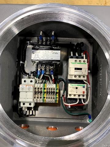
VFD drives are heart of motor control panel when it comes to starting and controlling 3 phase AC motors.
In lot of cases VFD are housed in vfd electrical panels to provide electrical, mechanical, environmental protection to VFD, motor, electrical system and user.
These panels require regular maintenance to work trouble free.
Here are Some Maintenance Tips
- Always inspect and clean or replace intake and exhaust filters, check if fans are working fine and the thermostats are calibrated correctly.
- Check any signs of VFD drive overheating, Inspect VFD for any dust or debris, clean if required.
- Check any sign for excessive humidity or moisture in vfd electrical panel, If any issues try to adjust the air flow, change the location of intake filter or panel or add anti- condensation heaters
- Check for loose connections, abnormal noise and check if motor is operating fine.
Motor Starters Explained: Types, Functions, and How to Choose the Right One
February 8, 2023
For different type of electrical motors and there are different type of motor starting technologies available. Adding more to that depending on the application, power availability and feature you require you may need more than combination of one technology.
What is a Motor Starter?
A starter (also known as a starter motor, cranking motor, or self-starter) is an electrical device that allows an engine to initiate an operation on its own by sending an electrical push of current to the motor. The motor starter safely starts, stops, and protects electric motors. It regulates the initial inrush current, reducing stress on the motor and connected circuits. Motor starters often include overload protection, contactors, and relays to ensure efficient operation and safety, making them essential components in industrial and commercial motor control systems.
How Motor Starters Work
A motor starter is an essential device used to control the flow of electrical current to a motor. It effectively manages the safe start, stop and protect functions. Motor starters work by controlling the flow of electrical current to a motor. They use contactors to close the circuit and start the motor, while overload relays monitor current levels to prevent damage from overheating. It regulates the initial rush current, reducing stress on the motor and connected circuits. Motor starters also provide crucial overload protection, ensuring the motor doesn’t draw excessive current during startup. This safeguards the motor and any connected equipment from potential damage and prolongs system life.
Key Components of a Motor Starter
- Contactor – Controls the flow of electrical current to the motor by opening and closing the circuit.
- Overload Relay – Protects the motor from overheating or overcurrent by interrupting the circuit if necessary.
- Control circuit – Includes push buttons or switches for starting or stopping the motor.
- Thermal or Magnetic Protection – Prevents damage caused by excess current or temperature.
- Enclosure – Provides housing for the components, ensuring durability and safety.
Applications of Motor Starters in Industry
- Manufacturing – Control machinery like conveyors, pumps, compressors and mixers.
- Oil and Gas – Manage critical equipment such as drilling motors and pipeline pumps.
- HVAC Systems – Regulate fans and compressors for heating, ventilation and air conditioning.
- Water Treatment – Operate pumps and agitators in treatment processes.
- Mining – Drive crushers, hoists and other heavy equipment.
- Agriculture – Power irrigation systems and grain elevators.
- Renewable Energy – Control motors in wind and solar energy systems.
- Construction – Operate concrete mixers and other motorized tools.
Cost and Maintenance of Motor Starters
- Cost Variability – Prices range from affordable manual starters to advanced, automated models, depending on size and features.
- Regular Inspection – Periodic checks of contacts, relays and wiring ensure reliability and prevent failures.
- Part Replacement – Components like contactors may need replacement due to wear over time.
- Cleaning and Lubrication – Routine cleaning and proper lubrication enhance performance and longevity.
- Troubleshooting – Addressing issues promptly minimizes downtime and maintenance costs.
- Quality Investment – High quality components reduce maintenance demands and improve overall system efficiency.
Types of Motor Stater
There are three main type of motor starters.
- Manual Motor starter
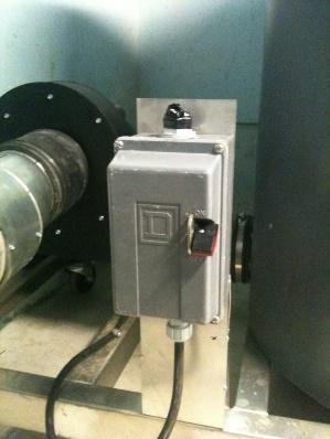
Manual motor starter is combination of a heavy-duty motor rated switch with a set of bimetallic thermal overload, this motor starter can be only turned on or off manually being in front of the starter but this will automatically trip in case of overload situation and you have to manually reset it.
- Magnetic motor starter
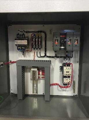
Magnetic motor starter is combination of a magnetic contactor and set of bimetallic or electronic overload device, this motor starter can be turned on or off manually being in front of the starter or remotely. This technology can also be integrated with other devices like sensors, float switches or PLCs to start or stop automatically
- Solid State Motor Starter
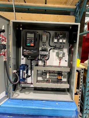
Solid state motor starter has all the feature of magnetic motor starter and additionally this can limit the inrush current of the motor, speed control of the motor and provide you monitoring data like current, voltage and torque.
Also Read : Tips to Update your Motor Starter
Factors to Consider for Selecting Motor Starter
1. Contactor Size & Line Power
The size of a contactor and the line power are related because the contactor must be sized appropriately to handle the line power of the motor it is controlling.
Line power refers to the electrical power that is supplied to the motor, typically in terms of voltage and current. The size of the contactor must be capable of handling the line power of the motor, meaning that it must be able to carry the current required by the motor without overheating or otherwise being damaged.
There are several factors that influence the size of the contactor, including the type of motor, application of motor, the voltage and current requirements, the duty cycle of the motor, Contactor are marked with voltage and motor horsepower they can run. In general, larger motors will require larger contactors, while smaller motors can be controlled by smaller contactors.
2. Overload Relay Range
An overload relay is a protection device used in motor power circuit to prevent motors from overloading or overheating. The overload relay range refers to the range of current values within which the relay will activate to protect the motor.
The overload relay range is set to match the full load current of the motor. The full load current is the amount of current required to operate the motor at its rated output power. The overload relay range should be set such that it will activate if the current exceeds the full load current of the motor by a certain percentage, typically between 10% to 25% of the motor rated current.
Some overload has fixed range so it is important to choose the right overload relay range for a specific motor to ensure that it will be protected against overloading or overheating. Other overload relays have an adjustable range to set. It is very important to set the range by figuring out the full load current of the specific motor, it duty cycle and application.
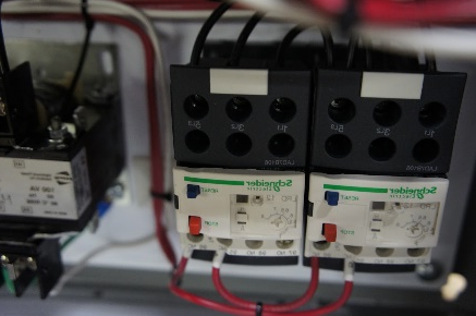
3. AC Coil Control Power
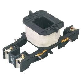
The AC coil control power of a contactor refers to the power required to energize the coil of the contactor to close the power and auxiliary contacts and energize the motor. The AC coil control power can be supplied by the same AC source as the motor, or it can be supplied by a separate lower AC or DC power source. 120VAC or 230V and 24VDC are most common coil control voltages in the industry.
Always make sure coil control power must be sufficient to energize the coil and close the contacts properly. Coil power consumptions is always listed on the contactor name plate.
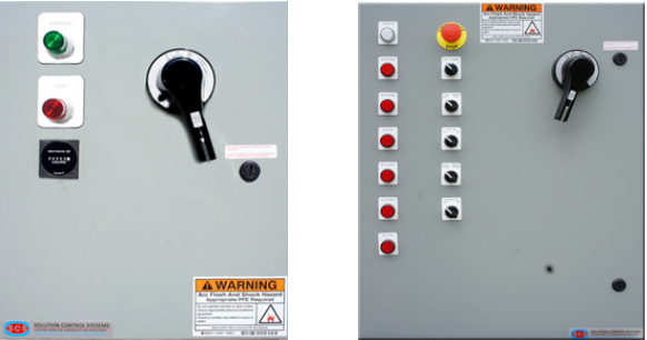
4. Enclosure Cover Buttons
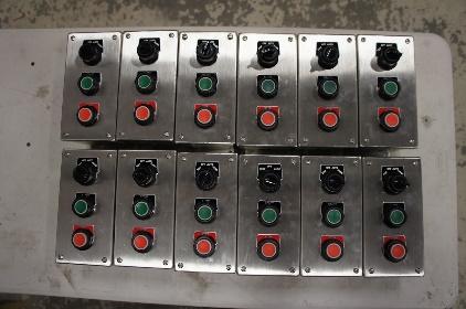
This is referring to switches or pilot lights installed on the door of the control panel enclosure.
There are few things to keep in mind when designing or installing these items on the enclosure door. Enclosures have an environmental rating which tell thee are indoor, outdoors or dust proof. The operators must have the same rating of the enclosure or above.
Some enclosures could be really tall, consider installing all the operable switches within human reach, A safe distance will be 6 feet when measuring of the working platform where a work will stand and operate these.
5. Full Torque at Zero Speed
“Full torque at zero speed” refers to the capability of an electric motor to produce its maximum torque output when it is not rotating or at a standstill. This is an important characteristic for applications where quick and powerful starting is required, such as in electric vehicles, drill presses, conveyors or some other industrial machinery. Motors with this capability are commonly known as “torque motors” or “zero speed torque motors”.
Variable Frequency Drives can be used to achieve full torque at zero speeds by adjusting the voltage to provide the correct level of power to the motor.
The frequency setting should be set to match the optimal operating frequency of the motor. High frequency will increase the torque, but also the heat generated by the motor.
Also Read: Useful Tips for Extending the Lifespan of Starter Motor
6. Cost, Size, and Thermal Considerations
The cost, size, and thermal considerations of a Variable Frequency Drive are important factors to consider when selecting a VFD for a specific application.
Cost: Mostly the cost of the VFD depends on the input voltage, size, features and brand. Typically larger and more advanced VFDs will be more expensive, while smaller and basic models will be less expensive. It’s important to balance the cost with the specific requirements and features needed for the application.
Size: The size of the VFD will depend on the motor power and the specific features required. Larger VFDs will be able to handle run larger motors and provide more advanced features, while smaller VFDs will be more compact and suitable for smaller motors.
Thermal considerations: The thermal performance of the VFD is a critical factor to consider. The VFD must be able to dissipate heat generated by the motor and the VFD itself, to avoid overheating and potential damage. The thermal performance will depend on the design and cooling system of the VFD, ambient temperature and the specific requirements of the application.
10 Signs You May Need to Consider Replacing Your Electrical Control Panel
Electrical Control panels require regular maintenance but at some point, these panels require replacement, make sure whenever you chose to buy a control panel it is built by a reputed industrial control panel manufacturer.
What Does an Electrical Panel Do?
Different control panel have different purposes, but most electrical control panels distribute power, control, protect and monitor equipment. An electrical control accepts the power from a power source like a utility panel board or generator and distribute with in the control panel with a use of circuit protection device like a breaker or fuse. Then that power runs through a power switching device like a power relay, contactor, soft starter, variable frequency drive and control the intended equipment in the field.
A Guide on Fundamentals of Electric Motor Starters
April 12, 2022
Electric motor starters and controllers play a crucial role in many electrical control systems. To assist you in grasping the essentials of motor starters better, we’ve put together this piece.
What is Electric Motor Starter?
To properly start and stop a motor, an electrical component is needed, i.e. starting motor. An electric motor starter acts as a relay, switching the electricity on and off. A starter, unlike a relay, offers overcurrent and low voltage safety. There are four primary purposes of a motor starter:
- Start a vehicle with caution
- Make a safe stop for a car
- Reverse a motor’s rotation
- Ensure that the motor is protected against overheating and overvoltage
Different Types of Motor Starters
Electric motor starters are devices used to safely start and stop electric motors while protecting them from damage. Common types of include Direct-On-Line (DOL) starters, which provide full voltage directly to the motor. Star-Delta starters, which reduce starting current by initially connecting the motor in a star configuration before switching to delta and Soft Starters which gradually ramp up voltage to minimize mechanical stress and electrical surges.
Why We Need a Starter with a Motor?

The frequent inrush from starting across-the-line might overload and harm the motor in applications that need many starts/stops (usually more than four per hour).
Also Read: 6 Considerations for Choosing the Best-Fit Starter Motor Control Technology
It can harm other equipment on the supply line if a considerable quantity of current is drawn from a bigger engine. As a result, a distinct technique is used to start most big motors. On-delay timers or programming of the control system should be used to stagger the commencement of many smaller loads coming on the line simultaneously.
How a Motor Starter Works?
A motor can be started manually or electrically. When using a manual starter, an ON/OFF lever or button must be manually shifted from the ON to the OFF position for the device to start. The power supply may be turned on or off by forming or breaking the connection.
Manual starts have the drawback of automatically resuming operation after a power outage, which might pose a safety risk. However, manual openings do not allow for automated control. Hence industry best practices discourage the usage of manual starters.
The contactor functions similar to a relay in an electro-mechanical starter. An energized coil magnetically pulls in the contacts that complete the circuit to the motor, enabling it to draw electricity. A lower voltage (usually 120V) is used to operate the power circuit, while a higher voltage (commonly 208V or460V) is used to power the system.
Also Read: How Soft starters Regulate Current in Induction Motors
What is the function of a starter motor?
An electric motor starter safely initiates and stops the operation of an electric motor. It controls the power flow, protecting the motor from overloads and electric faults. By regulating the initial inrush current it prevents voltage drops and mechanical stress. Additionally, it offers safety features like short-circuit protection and emergency shut off, ensuring reliable and efficient motor performance.
The importance of motor starters
Motor starters are crucial for the safe and efficient operation of electric motors. They regulate the high inrush current during startup, preventing electrical surges and minimizing mechanical stress on the motor and connected equipment. This extends the motor’s lifespan and reduces maintenance costs. Motor starters also provide essential protection against overloads, short circuits, and phase failures, ensuring safe operation, Additionally, they enable precise control over motor speed and torque, enhancing productivity and energy efficiency.
Conclusion
Electric motor starters play a vital role in ensuring the safe, efficient, and reliable operation of electric motors. By controlling startup currents, providing overload protection, and enabling precise motor control, they enhance equipment longevity and operational safety. Investing in the right motor starter not only protects valuable machinery but also optimizes productivity and energy efficiency, making them indispensable in modern industrial applications.
Overview and Benefits of Power Distribution Control System
Many intelligent field devices are available today, and protocols such as Profibus, Profinet, and Modbus make even the most complicated industrial processes easy to manage. Distributed Control Systems (DCS) or Power distribution control systems increase efficiency, quality, and dependability in the manufacturing process.
Power Distribution Centre: What Is Important To Consider?
March 16, 2022
A power distribution center plays a main role in determining how efficiently a data center works. Choosing the right PDU will go a long way in maintaining the seamless operation of your data center and improving its productivity in the long run.
Protective Relay : Working Principle, Types, Advantages & Its Applications
Protective relays are instrumental in monitoring and detecting problems in an electrical circuit. Based on their design, dimensions and local operating range, relays can be classified into different types for use in different areas.
What is a Protective Relay?
A protective relay is an electrical device designed to detect abnormal conditions, such as short circuits or overloads in power systems. It automatically triggers circuit breakers to isolate the faulty section, protecting equipment and ensuring safety. Used in switchgear and control systems, protective relays enhance system stability, minimize downtime, and safeguard personnel from electrical hazards.
A relay protection control device plays an important role in monitoring and detecting faults or abnormal conditions in the current, voltage and power flow in an electrical circuit. In the event of a fault, the device triggers the circuit breaker to detect and isolate the bad circuit from the rest of the power system. In doing so, protective relays help isolate/remove bad/abnormal and/or short-circuiting elements from the power system.
A protective relay can be classified based on three basic parameters – design, dimensions and operating range. Accordingly, based on these parameters, they can be differentiated into the following sub-categories:
Design:
- Sealed
- Open
- Hermetic
Dimensions:
- Miniature
- Micro Miniature
- Sub Miniature
Operating Range:
- Micro Power
- Low Power
- High Power
- Intermediate Power
Types of protection relays in power system
In power systems, protective relays are categorized based on functionality and technology. Key types include Overcurrent Relays for detecting excessive currents, Differential Relays for internal fault protection, and Distance Relays for transmission line protection. Voltage and Frequency Relays monitor abnormal voltage or frequency levels. Technologically, they are classified as Electromechanical Relays (traditional), Static Relays (solid-state), Digital Relays (microprocessor-based), and Numerical Relays with advanced programming and communication features for enhanced system protection.
Protective Relay Types
Solid State Relays
Solid-state components switch operations without moving any parts. These relays offer high power gains compared to other relay types owing to the less energy required for the switching operation. Examples include photo-coupled SSR and transformed coupled SSR.
Electromagnetic Relays
These relays use electrical, magnetic, and mechanical elements to perform the switching operation. They also use mechanical contacts and operating coils, with mechanical contacts opening or closing when the coil gets activated. Examples of electromagnetic relays include AC/DC relays, induction relays and electromagnetic attraction relays.
Hybrid Relays
These protective relays combine the use of electronic and electromagnetic elements to perform the switching operation. The electronic component rectifies the fault and the electromagnetic component relays the output. A good example would be a reed relay.
Thermal Relays
These relay protection control devices rely on temperature sensors to perform the switching operation. They detect an increase in temperature and switch the positions, isolating the faulty component. Thermal relays usually find their use in motor protection.
What are protective relays used for?
Protective relays are used to detect abnormal electrical conditions, such as short circuits, overloads, and ground faults, in power systems. They automatically trigger circuit breakers to isolate faulty sections, protecting equipment and ensuring safety. Widely used in switchgear and control systems, they enhance system stability, minimize downtime, and safeguard personnel from electrical hazards by preventing damage and maintaining operational continuity.
Protective relays are used to detect abnormal operating conditions in electrical power systems and initiate corrective actions to protect equipment, ensure safety, and maintain system stability. They play a critical role in safeguarding electrical infrastructure by preventing damage and minimizing power interruptions.
Primary Uses of Protective Relays:
Fault Detection and Isolation:
- Identify electrical faults such as short circuits, ground faults, and overloads.
- Trigger circuit breakers to isolate the faulty section, preventing damage and ensuring safety.
Equipment Protection:
- Protect transformers, generators, motors, transmission lines, and other electrical equipment from damage due to electrical faults.
- Prevent overheating, insulation failure, and mechanical stress caused by abnormal currents or voltages.
System Stability and Reliability:
- Maintain the stability of power systems by quickly clearing faults.
- Minimize the impact of faults on the rest of the power network to ensure continuous operation.
Selective Tripping and Coordination:
- Coordinate with other relays to selectively trip only the affected part of the system.
- Minimize power outages by isolating faults without impacting the rest of the network.
Safety and Personnel Protection:
- Prevent dangerous situations such as electrical fires, arc flashes, and equipment explosions.
- Protect personnel from electric shock and other safety hazards.
Monitoring and Reporting:
- Continuously monitor system parameters such as current, voltage, frequency, and impedance.
- Record fault data for post-event analysis and preventive maintenance.
What are the Key functions of Protective Relays?
Protective relays have key functions, including fault detection to identify abnormal electrical conditions, decision making to assess fault severity, and tripping to isolate faulty sections by triggering circuit breakers. They also provide system coordination for selective tripping, minimizing power disruptions. Additionally, protective relays offer monitoring and reporting, enabling real-time diagnostics and preventive maintenance to enhance safety and operational reliability.
Key Functions of Protective Relays:
- Fault Detection: Identifies abnormal conditions such as short circuits, overloads, or ground faults.
- Decision Making: Evaluates the severity of the fault and determines if isolation is required.
- Initiate Trip: Sends a signal to circuit breakers to disconnect the faulty section.
- System Coordination: Ensures selective tripping to minimize power disruption while maintaining safety.
What are the applications of protection relay?
Protection relays are widely used in power systems for various applications, including overcurrent protection to guard against short circuits and overloads, differential protection for transformers and generators, and distance protection for transmission lines. They also provide voltage and frequency protection to safeguard equipment from abnormal conditions. Used in switchgear and control systems, they enhance safety, system stability and operation continuity.
Common Applications of Protective Relays:
- Overcurrent Protection: Protects equipment from excessive current due to short circuits or overloads.
- Differential Protection: Detects internal faults in transformers, generators, and motors by comparing incoming and outgoing currents.
- Distance Protection: Used in transmission lines to measure impedance and locate faults.
- Voltage and Frequency Protection: Monitors abnormal voltage or frequency variations to protect sensitive equipment.
- Motor Protection: Guards motors against overload, phase failure, and overheating.
- Generator Protection: Protects generators from faults like overcurrent, under/over voltage, and reverse power flow.
What are the advantages of protective relays?
Protective relays enhance safety by quickly isolating faults, preventing equipment damage and electrical hazards. They ensure system stability and reliability by minimizing power outages and maintaining operational continuity. With fast and accurate fault detection, they reduce downtime and maintenance costs. Additionally, modern relays offer remote monitoring and control, enabling proactive maintenance and improved system management.
Protective relays offer several advantages that make them essential components in electrical power systems, especially in switchgear and control systems used in industrial applications. They enhance safety, reliability, and operational efficiency while protecting valuable equipment from damage. Key advantages include:
Enhanced Safety:
- Quickly isolate faulted sections, reducing the risk of electric shock, fires, and arc flashes.
- Protect personnel by preventing dangerous electrical conditions.
Equipment Protection:
- Prevent damage to transformers, motors, generators, and other electrical equipment from faults like short circuits, overloads, and ground faults.
- Prolong equipment lifespan and reduce maintenance costs.
System Stability and Reliability:
- Maintain power system stability by quickly clearing faults and preventing cascading failures.
- Ensure continuous power supply and reduce the risk of blackouts.
Selective Coordination and Minimizing Downtime:
- Coordinate with other relays to isolate only the faulted portion, minimizing power interruptions.
- Ensure that unaffected sections continue operating, reducing downtime and maintaining productivity.
Fast and Accurate Fault Detection:
- Rapidly detect and respond to abnormal conditions with high accuracy.
- Reduce fault clearing times, limiting damage and enhancing system resilience.
Remote Monitoring and Control:
- Digital and numerical relays offer remote monitoring, diagnostics, and control capabilities.
- Facilitate proactive maintenance by providing real-time system data and event logs.
Versatility and Flexibility:
- Can be programmed to provide protection for multiple types of equipment and faults.
- Easily adaptable to different system configurations and protection schemes.
Cost Efficiency:
- Minimize repair costs and operational losses by preventing extensive damage to equipment.
- Reduce insurance premiums by enhancing safety and risk mitigation.
Compliance and Safety Standards:
- Help industrial facilities comply with international safety and protection standards (e.g., IEC, IEEE, ANSI).
- Ensure regulatory compliance for electrical safety and operational reliability.
What Are The Different Ways to String Solar Panels?
February 8, 2022
Solar panels are becoming a common feature in many buildings. People are gradually turning to renewable energy resources, and solar panels are a cost-effective solution. This increased the demand for solar combiner boxes and installation services.
While the process is simple enough, it is important to determine the right method to string the solar panels and join them to the solar combiner box. The decision depends on the voltage and current you want to generate and supply to the control panel.
- Voltage is the measure of electric current/pressure that flows between two points. Household circuits have standard voltages, such as 110-120V, 220-240V, and 400-440V, to supply power to different appliances.
- Current is the transfer of electrons or electric charge from one point to another per unit of time.
- Electric power is when voltage and current are multiplied by each other. It is measured in watts.
Two Ways to String Solar Panels: Series vs. Parallel
1. Series Stringing of Solar Panel
Series stringing is when the positive terminal of one solar panel is connected to the negative terminal of the following panel and so on. This leads to a series of solar panels where the voltage increases with the addition of each panel but the amperage remains the same throughout. Series stringing is used when you want the solar combiner box to supply a fixed amount of voltage to the electric appliances/inverter.
Also Read: Qualities of a Reliable Solar Combiner Box
2. Parallel Stringing of Solar Panel
Parallel stringing is when the positive terminal of the solar panel is connected to the positive terminal of the next one, and the negative terminal is connected to the negative terminal. This results in a fixed voltage but increases the amperage of the circuit. This connection is used when you need to power inverters with fixed/limited amperage.
Read More: Solar Panel Wiring Basics: An Intro to How to String Solar Panels
Solution Control System designs customized solar combiner boxes confirming the UL1741 standard. Our combiner boxes provide protection and monitor the solar panels to ensure a continuous supply of current. We serve residential, commercial and industrial clients with varying requirements.
How To String Solar Panels?
Stringing solar panels involves connecting them in series or parallel to achieve the desired voltage and current. In a series connection, link the positive terminal of one panel to the negative of the next to increase voltage. For a parallel connection, connect all positives together and all negatives together to maintain voltage while increasing current. Ensure proper wire sizing, use combiner boxes if needed, and follow inverter specifications for efficiency.
Series Stringing of Solar Panels: How It Works & When to Use It
Series stringing of solar panels connects the positive terminal of one panel to the negative of the next, increasing the system voltage while keeping the current the same. This setup is ideal for high-voltage inverters and long cable runs, reducing power loss. Use it when matching inverter voltage requirements or in shaded areas where bypass diodes help maintain performance despite partial obstructions.
Parallel Stringing of Solar Panels: Benefits & Applications
Parallel stringing of solar panels connects all positive terminals together and all negative terminals together, maintaining the same voltage while increasing current. This setup is ideal for low-voltage systems and off-grid applications with battery storage. It improves reliability, as shading on one panel doesn’t significantly impact others. Use parallel connections when working with charge controllers or in systems requiring higher current output.
Series vs. Parallel Solar Panel Connection: Key Differences
Series and parallel solar panel connections differ in voltage and current distribution. Series connections increase voltage while keeping current constant, making them ideal for high-voltage inverters and long-distance transmission. Parallel connections maintain voltage but increase current, suitable for low-voltage systems and battery storage. Series setups are more efficient in high-sun conditions, while parallel setups perform better in partial shading.
How can we boost the efficiency of the Solar Panel?
Boosting solar panel efficiency involves optimizing panel placement, keeping surfaces clean, and using high-quality components. Position panels at the optimal tilt and angle for maximum sunlight exposure. Regular maintenance prevents dirt and debris from reducing output. Using MPPT charge controllers, efficient inverters, and cooling mechanisms also enhances performance. Additionally, reducing shading and using bifacial panels can further improve energy generation.
Choosing the Right Stringing Method for Your Solar Panels
Choosing the right stringing method depends on your system’s voltage, current, and shading conditions. Series stringing increases voltage, making it ideal for grid-tied systems with high-voltage inverters. Parallel stringing increases current, best for low-voltage battery storage and off-grid setups. Consider inverter specifications, wiring efficiency, and shading impact to optimize energy production and ensure reliable system performance.
Conclusion
Selecting the right stringing method is crucial for maximizing solar panel efficiency and meeting system requirements. Whether using series for higher voltage or parallel for increased current, proper planning ensures optimal performance. Regular maintenance, high-quality components, and strategic placement further enhance efficiency. By understanding these factors, you can design a reliable solar energy system tailored to your needs, ensuring long-term sustainability and energy savings.